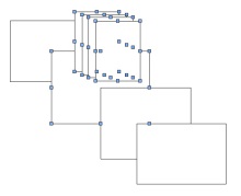
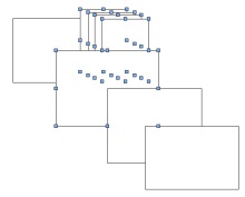
Navigatie overslaan

Hallo Gerard,

Volgens mij is het een euvel dat VW altijd heeft gehad en ik kan me niet voorstellen dat het nog bestaat. Maar het bestaat echt nog. Heel vaak als ik lichamen wil ‘adden’ krijg ik het bericht dat ik de geometrie moet aanpassen. Ik heb het gevoel dat dit vooral voorkomt bij symmetrische lichamen. Vaak voeg ik eerst een a-symmetrisch lichaam ergen aan toe en dan wil het soms lukken. Ook het berschuiven van b.v.een honderdste millimeter geeft wel eens resultaat. Het blijft modderen. Is hier iets aan te doen?
Groet,

L.S.

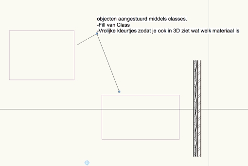
Ik heb. een paar eigen regels op gesteld:

  1. Snaps op hoekpunten en dergelijke moeten loepzuiver zijn. (is al een probleem op zich in 3D)
  2. Polylines (in een extrude of sweep) mogen geen gaten hebben. (Gaat op een zeker moment mis met latere add en subtract solids)
  3. Polylines mogen absolute geen lussen in de zijden hebben.
  4. Polylines en polygons moeten gesloten zijn.
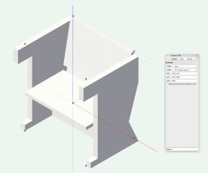
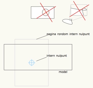
  5. Het model en de pagina moeten zo dicht mogelijk bij het interne nulpunt liggen.
  6. Houd het aantal geneste bewerkingen zo klein mogelijk. Vooral subtractions kunnen vaak gecombineerd worden in 1 subtraction.
  7. Om Meshes aan de praat te krijgen kan het nodig zijn een kleine cube aan de Mesh te “adden”.
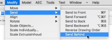
  8. Mocht een Solid function niet werken, probeer dan eens het model te flippen, dan de solid functie toe te passen en daarna het model weer terug te flippen.

Vectorworks 2016ScreenSnapz013

Met vriendelijke groeten,

Gerard Jonker

The Question:

Hi All,

I was just wondering if anybody knows of any ‘advanced’ Stacking Order tools?

We have a complex 2D elevation of a multi-tiered auditorium I’m currently working on. Sometimes new geometry needs to be in a specific place in stacking order to display correctly, but there can be a huge number of them (lets say 5-50 ‘stacking’ layers?). If I need something to stack at say, 25 out of 50, this is quite time consuming!

This may end up being one for the wishlist, but I’m imagining a tool which allows you to move the stacking order of an object to match another object (i.e. just in front or just behind)

Does anything like this currently exist?

Thanks,
A

The Answer:

In the very old days the Send to Back function would also revert the drawing order of the objects selected. That bug/feature was killed by the powers that be. That feature-bug however was ideal for solving situations as mentioned. So I wrote a little thingy called Reverse drawing order. That would be enough to solve your problem, although it needs to be called twice. Just a little tweaking was enough to rebuild it into Send behind.

Select the objects you want to send behind another object and select that object, too. Then call the function and voilá:

Vectorworks 2016ScreenSnapz001Vectorworks 2016ScreenSnapz002Vectorworks 2016ScreenSnapz003

Download:

SendBehind.vsm

However:

Unless you are tweaking a “Convert to 3D polygons” model (Who uses that function still, nowadays??? it is far nicer to render a hidden line in foreground of a Final Quality Renderworks in a viewport) you wouldn’t need these function if you, like Boh suggests, used groups and symbols to draw a more object oriented “model” (a 2D drawing can be a model, too). By making sure you minimize the stacking amount to 3-5 objects it is easy to make corrections later. As soon as you go over your personal limit (for me that is 3 objects) include a group some of these objects belong more together than others so you can group them The parts of a window and the curtains are more likely together than the balcony in front of them. This way it is very easy to send, inside the group, the curtains behind the window and outside the group the balcony in front of them.

Just my 2cts (or 4,  who is counting).

The whole thread:

The whole thread can be found here:
https://forum.vectorworks.net/index.php?/topic/54780-geometry-stacking-order/

The Question:

Hi, 

Many a time where you happened to want to create a library but found it too cumbersome because the record information must be written directly in the resource manager rather than a spreadsheet?

Is it possible to write existing record information inside of a symbol to the symbol definition please? This would tremendously expedite symbol and library creation.


First of all you need to know that the Symbol in your drawing is an Instance (a placeholder, a locus, if you like) that redirects the program to the Symbol Definition in the Resource Manager when it needs to draw the Symbol. Everything you do with the Instance in the layer doesn’t affect the definition. (Editing seems to contradict that, until you realise the program simply brings you to the definition to edit). The Instance can have a record attached, but that doesn’t automatically go for the Definition. If a Definition has a record the Instance automatically has the same record and will initially show the same (Default) data. Changes to the data in the Record of the Instance will NOT be brought to the Record of the Definition.

So when you setup a library document with a lot of symbols with records you have to edit the default values of the records at Definition level. Instead of bringing all data from the instances to their definitions by hand we can of course write a little script that does it for you:

Move Rec from Inst to Def.vsm

It is a plug-in menu command.

  1. Unzip
  2. Place into Plug-Ins folder inside User folder *
  3. Restart Vectorworks
  4. In Vectorworks go to Menu bar Tools:Workspaces:Edit The current Workspace
  5. Drag the menu from left to right in a menu of your choice

To find the User folder

  1. Go to the Vectorworks preferences
  2. Click the Tab called User Folder
  3. Click either “Reveal in Finder” or “Explorer”

If you select no objects, the command will run through your document and execute the script for each symbol instance it encounters, else it will only run on the selected instances.

Hope this helps.

Reaction 1:

HOLY (*&#)$(*&#($*&#$ !!!!!!!!!!!!
Gerard, you are THE MAN! This works like a charm!!!

Reaction 2:

Ok cool. Thanks Gerard. I hadn’t imported a plug-in before so have learned something new today!
Bonus is that it actually works!

The full conversation can be found on the Vectorworks forum.

On 1 Jan 2018, at 16:43, . . . .  wrote:
Happy New Year All,

Are there any tutorials for creating a VW PIO?  Specifically, I am looking to create a PIO that allows me to insert custom length church pews based on the length I enter.  Or if something like this exists, I’d be all ears.
Thanks much!

. . . .

Hi . . . . ,

Small note: In contrast with symbols that help reduce document size: the PIO is drawn in place and will actually increase the document size as if you drew the objects yourself.
You start with drawing your Church Pew in an other wise empty file (really empty).
Make sure to extrude while you are in the Right view. This makes creating the PIO so much simpler
Give the extrusion of the seat (the length of the Pew) and easy to recognise number. (Sorry for my evil sense of humor, but I don’t believe in the magic forces of numerals, like 13 or 7)
Maybe you want to make the arm rests into symbols with the name ‘Arm_Rest’ This saves a bit on document size.
Drawn Pew:

Vectorworks 2018ScreenSnapz019

Export the whole file as a script:
 Vectorworks 2018ScreenSnapz018


Open the script in a simple Text editor. I’m a big fan of BBedit and Text Wrangler as they don’t add anything to the document.
MailScreenSnapz006
Now open the Plug-in manager and create a Linear Object:Vectorworks 2018ScreenSnapz014


Check the Definition to add more variables if you need them.
The variable LineLength is standard for a Linear Object.
Vectorworks 2018ScreenSnapz015

Now Edit the script and type the following:
Procedure CP;
const gSymbname = ‘Arm_Rest’;
var gCPlength : real;
begin
gCPlength :=
end;
Run(CP);
If you copy from this site you may want to paste in and copy  from BBedit to flush unwanted characters. (BTW Your script may start on line one).
Vectorworks 2018ScreenSnapz016
Now add a ‘P’ followed by the name of variable to to read that variable into your script.
To prevent typos you can read the var name from the menu Parameter… and choose the variable in the next dialog:
Vectorworks 2018ScreenSnapz020

Vectorworks 2018ScreenSnapz021

 Now your script will read something like this:
Procedure CP;
const gSymbname = ‘Arm_Rest’;
var gCPlength : real;
begin {main}
gCPlength := PLineLength;
end; {main}
Run(CP);
It is good practice to keep many comments in your scripts between {} . You will always regret later not commenting the most simple decisions you take now.
Test run the script by clicking on the sprocket button
Vectorworks 2018ScreenSnapz022
 First check the existence of the symbol Arm_Rest:
if Getobject(‘Arm_Rest’) = NIL then Create_Arm_Rest;
Create_Arm_Rest
Will be a sub procedure in your code.
The function Getobject returns a handle. I don’t need the handle variable, I can immediately check if it is empty ie: NIL.
Procedure CP;
const gSymbname = ‘Arm_Rest’;
var gCPlength : real;
 
Procedure Create_Arm_Rest;
Begin {Create_Arm_Rest}
end; {Create_Arm_Rest}
 
begin {main}
if GetObject(‘Arm_Rest’) = NIL then 
Create_Arm_Rest; {check for the existence of the symbol, if not create it}
gCPlength := PLineLength; {reads LineLength variable back into script.
end; {main}
Run(CP);
Now copy the {Symbol Library Entries} and paste them in the Procedure Create_Arm_Rest:
BeginSym(‘Arm_Rest’);
NameClass(‘None’);
BeginXtrd(0,50);
ClosePoly;
PenSize(2);
PenPat(2);
FillPat(1);
PenFore(0,0,0);
PenBack(65535,65535,65535);
FillFore(0,0,0);
FillBack(65535,65535,65535);
boolResult := SetDefaultBeginningMarker(0,15,0.125,0,34,0.05,FALSE);
boolResult := SetDefaultEndMarker(0,15,0.125,0,34,0.05,FALSE);
Poly(
-522.5,0,
-522.5,55.001292239404421,
-445,55.001292239404421,
-445,670,
-600,670,
-600,800,
0,800,
0.000000000000035,559.264705882353269,
-105,235.000000000000057,
0,0
);
objectHandle := LNewObj;
SetDropShadowData(objectHandle, 0,0.1,0.05,#315.0000000000d,75,0,0,0);
EnableDropShadow(objectHandle, FALSE);
 
objectHandle := LNewObj;
SetObjectVariableBoolean(objectHandle, 1160, FALSE);
boolResult := SetEntityMatrix(objectHandle, 0,0,0,0,-0,0);
 
EndXtrd;
ResetOrientation3D;
Rotate3D(#90.00000000000d,#-0.0000000000000d,#90.00000000000d);
Move3D(-25,300,0);
objectHandle := LNewObj;
SetDropShadowData(objectHandle, 0,0.1,0.05,#315.0000000000d,75,0,0,0);
EnableDropShadow(objectHandle, FALSE);
 
 
EndSym;
SetSymbolOptionsN(‘Arm_Rest’,0,1,”);
tempHandle := GetObject(‘Arm_Rest’);
SetObjectVariableBoolean(tempHandle, 130, FALSE);
objectHandle := LNewObj;
SetDropShadowData(objectHandle, 0,0.1,0.05,#315.0000000000d,75,0,0,0);
EnableDropShadow(objectHandle, FALSE);
If you test run the script you will see a few errors. That is because the copied creation code uses a few handles and a boolean.
Add them to the header of your sub procedure:
Procedure Create_Arm_Rest;
var objectHandle, tempHandle : Handle;
   boolresult : Boolean;
Begin {Create_Arm_Rest}
BeginSym(‘Arm_Rest’);
NameClass(‘None’);
. . . 
SetDropShadowData(objectHandle, 0,0.1,0.05,#315.0000000000d,75,0,0,0);
EnableDropShadow(objectHandle, FALSE);
end; {Create_Arm_Rest}
Now in BBedit in part of the Object creation code look for our value ‘666′ and  replace it for our variable gCPlength
 BBEditScreenSnapz001


Paste the extrude text into the Create_Seat procedure.
In the {main} part of your code you need to call the procedure.
Create a procedure for placing the armrest symbols:
Procedure Place_Symbol(x_pos :real);
You give it a new variable, that variable needs to be used in the code:
 BBEditScreenSnapz002


Procedure Place_Symbol(x_pos : Real); {Places the symbol Arm_Rest}
var objectHandle : Handle;
Begin
Symbol(‘Arm_Rest’,0,0,#0.0000000000000d);
ResetOrientation3D;
Rotate3D(#-0.0000000000000d,#-0.0000000000000d,#-0.0000000000000d);
Move3D(x_pos,-300,0);
SetObjectVariableInt(LActLayer, 101, 1);
objectHandle := LNewObj;
SetDropShadowData(objectHandle, 0,0.1,0.05,#315.0000000000d,75,0,0,0);
EnableDropShadow(objectHandle, FALSE);
end; {Place_Symbol}
The place_Symbol procedure needs to be called from the main part of your code, twice.
begin {main}
if GetObject(‘Arm_Rest’) = NIL then 
Create_Arm_Rest; {check for the existence of the symbol, if not create it}
gCPlength := PLineLength;
Create_Seat;
Place_Symbol(-25);
Place_Symbol(gCPlength + 25);
end; {main}
Check your code by test running it.
If there are no errors, then close the editor and the manager.
Go to the workspace editor.
Click on tools and drag the Church Pew from left to right in the desired tool set.
Here to download the VectorWorks 2018 PIO that I made while typing this VectorScript lesson.


In 2010 I wrote the following article on the Vectorworks forum:


What it looks like from my position is that the whole “2D objects on 3D planes” idea was only introduced to assist the Push & Pull tool. If that is so, I would have preferred a new set of tools that draws the 2D objects on those planes. (Directly on the object clicked on, rather than on separate planes that have to be established first. More on that later).

Now it looks like we want to have 2D objects on several planes, which in fact we don’t want at all (well, I don’t want that). We want 3D objects on planes through our model, not 2D objects. The advantage of 2D objects is that they can have several kinds of graphics attached to them, but instead of spreading 2D objects through space, it would have been nicer if we got more flexibility in texture handling on 3D objects, and more control over 3D objects. Like 3D rotation of textures (rather than rotating the texture in it self) and assigning different textures to different sides of objects, like we can with walls.

The downside of 2D objects floating on other planes in space is that it is very unclear how these are going to be treated by the render engines and how they will export to DWG on one side, C4D in the middle and IFC on the other side of the spectrum.

BTW I like the idea of the Push and Pull tool very much, it looks a bit inspired from Sketch Up though. All other things that were inspired by other programs are far better implemented than in the original programs, like References and ViewPorts. In the case of the Push and Pull tool, that is not very clear yet.

One point of improvement might be the control over the objects that are drawn on the surface of a 3D object. For instance: a separate tool that draws the rectangle directly on an objects face. It would have an optional first click on a corner of the 3D object, then a 2nd click along a side, VW would still not know which surface it would be, the 3rd click would reveal to VW the surface and finish the rectangle or oval. When you’d look in the OIP you’d see the X and Y values as distance to that first click. This would give control over the object drawn. This is already possible in VW 2011 but it requires the set up of a separate working plane. While the tool could do that immediately the moment it recognizes the 3D objects side clicked on.

One last thing: I noticed the default setting of the plane is Layer plane in case of a new file. I would suggest to default to screen plane as it used to be. VWs object handling in screen plane is still much better than its “plane object” handling. Also, when I set the plane to default to Screen Plane, it sometimes, by itself switches back to Layer plane or 3D plane. Very annoying.

Editing an extrude, shows me the object in “Extrude Plane”. Especially for extrusions, it might be far better to look at it face on. The same goes for Editing symbols. Symbols are created in their easiest orientation and then placed in drawing under strange angles. When I edit the symbol I would like to be in straight orthogonal mode.

I do see it might come in handy some times and I do admire the fact that you are able to rotate it in this way. I noticed I can do a few things with the “Plane Mode” buttons next to the views, but once hitting the “Active Layer/Symbol Plane Mode” button should return me to old fashioned Front and Rights (etc) views inside the symbol.

Thanks,
Gerard   ”

It looks like nothing, I mean really nothing, has ever been done with these comments.

Ik ontving net jouw mail met de aanbieding van de upgrade-actie van Vectorworks. Mooi.
Ik zat al te dubben om te upgraden, want ik kreeg exact  dezelfde aanbieding van
Design=expres, die kost ook hetzelfde.
Ik wil wil graag bij jullie weer terug, maar ik aarzel een beetje. Kunnen jullie dezelfde VSS- service geven als bij Design=expres ?

Het is dezelfde actie. Naast de VSS van Design Express krijg je natuurlijk ook onze plug-ins als je de VSS via Jonker & Wu bestelt.

Hoe gaat het in zijn werk?

U ontvangt van mij en Enya-CAD een offerte. Print deze uit, tekenen, scan/foto maken en terug mailen naar “post at jonker-wu.nl”.
Vervolgens krijgt u uw VW licentie nummers en de factuur voor het eerste jaar VSS. U krijgt ook het contract met Design Express. Ook dat moet getekend op gestuurd worden. Let op, op de offerte en in het DE contract staat dat u akkoord gaat met de stilzwijgende verlenging van de VSS. Zorg er voor dat als u wilt stoppen met de VSS, in dit geval kan dat pas na twee jaar daarna natuurlijk jaarlijks, dat u dat dan in Mei van het lopende jaar opzegt. Als u een dag te laat bent zit u er weer voor een jaar aanvast.

Is het trouwens niet mogelijk de upgrade te doen en gelijk de VSS op te zeggen per einde twee jaar?

Ja, dat kan wel, maar als je dan later in mei 2019 wellicht toch verder wilt in de VSS gelden dan de prijzen en voorwaarden van dat moment, terwijl nu een prijs van 615,- wordt gegarandeerd voor het daarop volgende jaar. Wij adviseren dus: opzeggen in Mei 2019. Dan krijg je nog net voor het eind van de VSS de 2020 opgestuurd.

Renderworks wordt niet genoemd!

Klopt. Renderworks wordt niet meer los verkocht, het zit standaard in Vectorworks Fundamentals (en dus ook in Architect, Landmark of Spotlight).

Werkt Vectorworks 2018 of hoger wel op mijn computer?

Check even de system requirements voor VW 2018. Sowieso is VW 2018 een trage starter. Een Solid State (Hard) Drive maakt dat voor een grootdeel weer goed.

Blijft na het stopzetten van de VSS die laatste versie, Vectorworks 2020, dan wel doorwerken zonder het VSS abonnement?

Na het stopzetten van de VSS blijft de laatste versie voor eeuwig doorwerken, tenminste dat is op dit moment de politiek.

Krijg ik installatie software of een upgrade pack.
Ik wil nml mijn oude 2013 het liefst  ook nog laten draaien.

Jonker & Wu vraagt altijd of Vectorworks Inc. de oude versies draaiend wil houden.
De nieuwe VectorWorks is sowieso een los programma naast de oude.


 Rotterdam 21-11-2017
Vectorworks Upgrades zijn de laatste paar jaar behoorlijk prijzig geworden. De meeste van onze klanten stelden upgrades gewoon wat langer uit en eigenlijk werkte dat prima.  Mocht u toch al denken aan upgraden dan is dit wellicht een goed moment omdat te doen.
Op dit moment is er een upgrade actie, die loopt tot vrijdag 24 november 2017. We kunnen nu toch oudere licenties upgraden en bovendien voor een heel scherpe prijs:
Stap nu in een 2 jarig VSS contract en ontvang upgrades naar Vectorworks 2018, 2019 en 2020 zonder bijbetaling.
Mocht u weer uit de VSS willen stappen doe dat dan in de maand Mei van het laatste jaar, anders wordt het contract stilzwijgend verlengd en daar zijn ze keihard in.
We kunnen deze promotie nu aanbieden voor 2x het jaarbedrag van de VSS: 
Fundamentals: 2x 440,- = 880,- per licentie.

Architect: 2x 615,- = 1230,- per licentie.
Spotlight: 2x 615,- = 1230,- per licentie.
Landmark: 2x 615,- = 1230,- per licentie.


————————– Extra informatie ————————–
Overstappen van Fundamentals naar Architect:
Eerst de overstap maken, die kost 800,- euro en dan de VSS upgrade actie. Totaal wordt dan 2030,-
Ter vergelijking volgen hieronder de nieuwprijzen:
Nieuwe Fundamentals licenties kosten 1995,-.
Voor 440,- euro extra kunt u die ook in de VSS onderbrengen, te betalen in de maand Augustus volgend op de aanschaf.
Nieuwe Architect licenties kosten 2795,- .
Voor 615,- euro extra kunt u die ook in de VSS onderbrengen, te betalen in de maand Augustus volgend op de aanschaf.
 

en de Upgrade prijzen zoals die gelden buiten de actie:


-> VW 2018
2017
2016
2015
  2014*
Fundamentals 
 700,-
 1000,-
 1495,-
nieuwprijs
Architect
980,-
 1400,-
 2095,-
nieuwprijs
SpotLight
980,-
 1400,-
 2095,-
nieuwprijs

*) Buiten de actie kunnen we dus maar over drie jaar terug Vectorworks licenties upgraden, echter tijdens deze actie kunnen we alle Vectorworks versies upgraden, zelfs vanaf Vectorworks 8.
————————– kleine lettertjes ————————–
Genoemde prijzen zijn exclusief BTW
Stuur me uw bestelling vóór Vrijdag 12:00 uur. 
We verwachten grote aantallen bestellingen, om niet in cashflow problemen te geraken sturen we u de rekening direct na ontvangst van uw bestelling met het verzoek deze zsm te voldoen.
 
Met vriendelijke groeten,
Gerard Jonker
Jonker & Wu                         ism                   Enyacad
Mathenesserlaan 294                                   Van Critterstraat 44b
3021 HV Rotterdam                                      3022 LL Rotterdam
010 4770747                                                    010 2132841
post@jonker-wu.nl                                       info@enyacad.nl

Beste Gerard,

Wat zijn de voordelen van de Reshaper menu functie boven het Reshape tool?

Groet,
Tom

Beste Tom,

de Reshaper (menu) functie is iets heel anders dan het Reshape tool.

Reshaper is een Plug-in geschreven door Raymond Mullin van Sirius Solutions.
Vergelijk Reshaper meer met een verbetering/aanvulling op het Object Info palette. Vooral in 3D.

Een oud probleem van de het Object Info Palette is dat hij de focus vasthoudt. Het is een tijdje weggeweest, maar weer helemaal terug in 2017. Daarvan heeft Reshaper geen last omdat het direct weer gesloten wordt. Dit maakt Reshaper sneller in gebruik dan het OIP. Maakt dat het Object Info Palette overbodig? Nee. Ik heb graag het OIP open staan, zodat ik direct informatie krijg over het geselecteerde object. Maar ik gebruik het steeds minder voor het bewerken van die geselecteerde objecten, in plaats daarvan gebruik ik liever Reshaper.

Voor veel objecten doet Reshaper het beter dan het Object Info Palette.  Ik moet toegeven, Reshaper werkt niet op alle objecten, maar het zijn er wel veel. Hieronder een beperkt aantal voorbeelden van de objecten waar Reshaper wel op werkt met het bijbehorende Object Info Palette.

• Lengte en Breedte van een rechthoekige polygon:
vectorworks-2017screensnapz025

• Koorde en andere ankerpunten bij een cirkelboog:
vectorworks-2017screensnapz026

• Startpunt en Reverse (tekenrichting) voor 2D en 3D polygonen. Soms erg belangrijk:
vectorworks-2017screensnapz028

• Een extrusie met ankerpunten bewerken, ook in andere  views:
vectorworks-2017screensnapz027

• Een 3D polygon met ankerpunten bewerken, ook in andere views.
vectorworks-2017screensnapz029

• Absolute rotatiehoek van 3D symbolen.
vectorworks-2017screensnapz031

“lijnen” in 3D. het OIP ziet deze als polygonen, maar als je ze als lijnen kunt bewerken, dan kun je er opeens hele leuke dingen mee doen tijdens de opbouw van een complex model.
vectorworks-2017screensnapz032

Met vriendelijke groeten,
Gerard

Gerard,

de vraag van de vrijdag is er een, die ik me al zolang afvraag:
is er in VW misschien een instelling, die regelt dat de lijnen van objecten in de achtergrond van een doorsnede een bepaalde dikte krijgen (lees: heel dun en fijn)?

Zou mooi zijn.
Ik hoor het wel!
Goede vrijdag en weekend alvast.

Ja, dat kan en is vrij eenvoudig.

Hieronder een simpel tekeningetje. Ik zet graag mijn tekeningen zo op dat ik classes gebruik voor de diverse materialen zodat ik Fill en Lijndikte kan aansturen met die classe.

vectorworks-2016screensnapz043

Strikt genomen hoeft dat niet, maar dan moet je er voor zorgen dat de objecten de Fill en de Lijndikte hebben die ze in de doorsneden moeten tonen. Is dat hetzelfde als bij de plattegrond? Dus liever met classes werken denk ik.

Maak een extra class aan.
– Let op dat je “Use at Creation” aan zet.
– Houd de Fill wit
– Kies een lijnkleur en lijndikte (lees: Licht en dun)

vectorworks-2016screensnapz037

Selecteer alle materiaal classes in Viewport enklik op de Edit.

vectorworks-2016screensnapz040

Geef de geselecteerde classes een zwarte lijn kleur en een iets dikker lijn (0,70 is wellicht wat overdreven).
Raak instellingen die je niet wilt veranderen niet aan.

vectorworks-2016screensnapz041

Stel de section Viewport in zoals jij dat graag hebt.
Kies bij “Objects Beyond Section Plane” :
– Fill use class:Use Class: De extra class die je net hebt aangemaakt.
-Line Style: Use Class: De extra class die je net hebt aangemaakt.

(Bij Display kun je ook de onderdelen van een spouwmuur laten tonen).

vectorworks-2016screensnapz039

Resultaat:
vectorworks-2016screensnapz042

On December 5th 2016 a new version of Able2Extract was released by Investech.com.
Reason enough to test drive it as it is an important addition to a Vectorworks® Fundamentals for a mere 150,- $US. Even when you do have Vectorworks Architect, Landmark or Spotlight you might find Able2Extract useful.

PDF

Like the last time, I made a simple testfile and, like the last time, the best graphic reproduction of the PDF is by simply importing the PDF as PDF or as an Image file.
In Vectorworks Fundamentals you don’t have the ability to Ungroup a PDF, but in the other versions you have and you immediately see where the snappoints came from. Under the image lies a set of simple objects without fill. Mind you that the shape of the Polyline has altered. Most annoyingly: the Text is all gone. Big BOOO! for Vectorworks!

Able2Extract

Now let’s have a look at the Able2Extract route.
Of course, the first thing we notice is the lack of an Export .vwx button. Come on guys. Translating into a VectorWorks script is not that hard. Drop me a line and I’ll lend you a hand. Ok, we’ll take the DWG route.

Select prior to convert

In this version you have to select the data you wish to export. Although this may feel cumbersome it also has it advantages. Still it would have been nice if A2E would allow you to select the page in the left column and accept that as a selection of all objects on that page.

DWG

Then the data is exported. In our case to DWG. Don’t forget to set the scale.
Back in Vectorworks import the data into a new file and copy it to your destination file. Never Import a DWG into an existing drawing file and never continue to work in an imported DWG. Always do the copy action!!! This warning goes for all DWG files imported into Vectorworks, not only the Able2Extract DWG’s.

Analysis

As you can see in the last image all objects are doubled. Fill is separated from contours. This is a DWG draw back. This is why we would appreciate a “Convert to .vwx” button so much. The fluent Polyline and circle are translated into Polygons. Although that is a pity, it is actually the best way to preserve the shape of the objects. Thumbs up for Able2Extract.
There is also a thumbs down for Able2Extract: The previous version allowed for Layers to be preserved. Now the layers are gone. A2E has made a few generic Layer names to distinguish between fill, contour and text objects. Vectorworks has excellent selection tools so there is no need for silly Layer names, maintaining the original Layer (Class) names would be highly appreciated. The Dash line lost its dash and became continuous. Last and least: The line weights are gone.

pdf_in_vectorworks

This is the testfile I made. Imported as PDF into Vectorworks. Only the white background and the rounded pens give away it is not a snapshot of the original Vectorworks file.

pdf_in_vectorworks_ungrouped

The imported PDF Ungrouped. Vectorwoks didn’t convert the Polyline to polygon and screws up the shape of the object.

dwg_imported

The Able2Extract DWG imported into Vectorworks. First things to notice are the lineweights gone. But stacking filled objects survived the conversion.

analysed

Gradients are split into tiny rectangles with a color, most likely Vectorworks did this prior to export and polygons and circles are converted to polygons. Fills are split from their contours. The Dash line lost its dash.

One more thing

Able2Extract doesn’t accept files dropped on the Application icon. Even when you force it to open by holding the option + Command keys it won’t. You can however, drag files into the Able2Extract window once it is open.

finderscreensnapz003

Able2Extract is made by Investech.com from Cananda.
Vectorworks® is made by Vectorwoks Inc from USA, a Nemetschek Group company.